Virtual Optics

Announcements, requests and support regarding SkIndigo - the Sketchup / Indigo exporter.
Post Reply
5 posts • Page 1 of 1
Cyberdactyl
Posts: 26
Joined: Sat Jun 23, 2007 2:48 am

Virtual Optics

Post by Cyberdactyl » Thu Oct 01, 2009 1:59 am

Hi everyone,

I posted this at Sketchucation and thought it might be pertinent here. Also was wondering if anyone else has experimented with this ability of Indigo. . and I suppose, most any rendering engine.

* * * * * * * * *

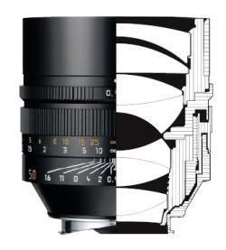
After much experimentation with Indigo's material attributes, most especially, mirroring and glass, and the refraction index, for quite some time, I've managed to re-image an object entity in SU through a refractor-type optical system using Indigo. I used a modified Kellner-type eyepiece, more closely resembling a RKE. I used THIS site to help me develop some basic shapes and refractive indexes.

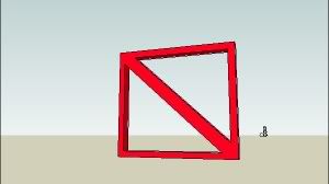
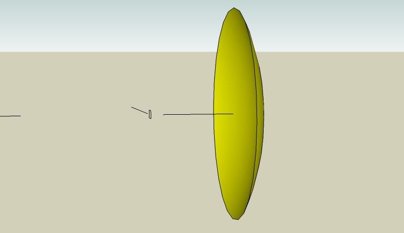
Here's the object I imaged and the optical setup in the distance. The distance ratio of the imaged object (the red slashed square) to the objective lens in relation to the objective and the 'eyepiece assembly plate' is 16 to 1.
Image

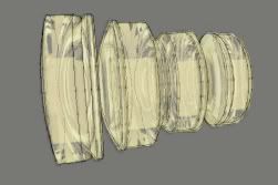
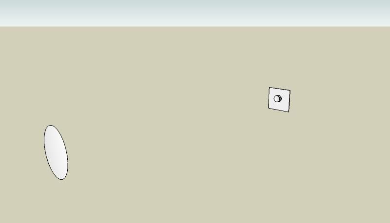
Here's a view of the objective lens and the eyepiece assembly.
Image

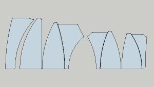
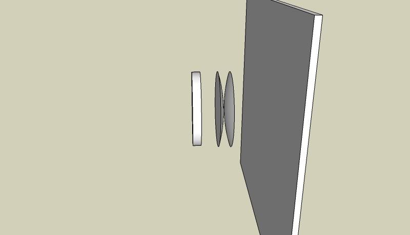
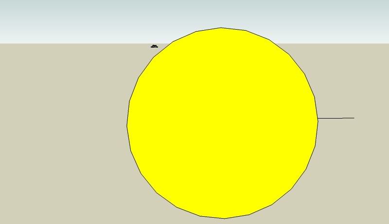
And the focusing or eyepiece assembly. I've changed the lenses to monochrome so they can be seen.
Image

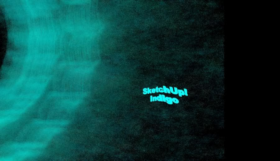
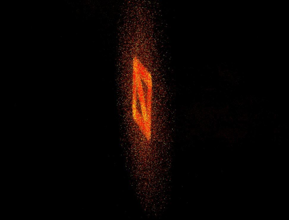
And finally the rendered image on the receiving plate.
Image

The, newtonian-type system below was a bit harder because I needed to get the parabolic shape of the main mirror close to perfect. . .or as in the "the real world", get the wavelength error within several angstroms of, say, yellow light. A "real" telescope mirror has to be MUCH more accurate than what I am doing of course.

Image

Image

Image

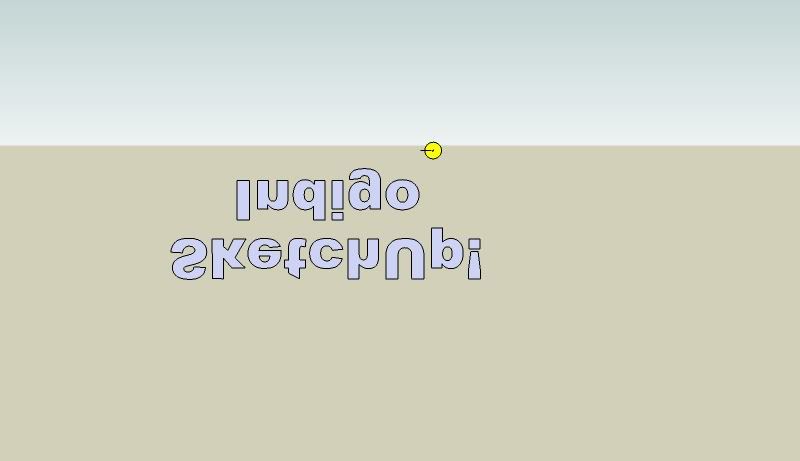
I've 'cheated' slightly here, in that I am not using eyepieces, and only letting the focus point of the image impact at the receiver plate. This would not allow a 'virtual eye' to see the image, as the image is crossing at the plate plane, and not traveling parallel. The imaged "SketchUp Indigo" was very close to the reflector. The ratio from the image to the receiver plate in comparison to the receiver plate to the top of the sagitta of the parabola is a modest 6 to 1, so I get a nice crisp image.

Image

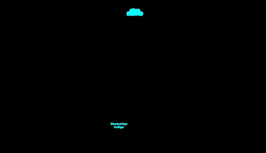
The below pic starts to show the error either in Indigo's ray tracing algorithm or the preciseness of my parabolic surface. I imagine it's my inability to draw an exact parabolic surface. The ratio here is a huge 320 to 1. Not much for a real optical system, but still kinda impressive in a virtual environment, not designed to do such.

Image
Last edited by Cyberdactyl on Thu Oct 01, 2009 12:42 pm, edited 2 times in total.

remus
Indigo 100
Posts: 133
Joined: Fri May 02, 2008 8:07 am

Re: Virtual Optics

Post by remus » Thu Oct 01, 2009 2:48 am

You could try turning subdivision smoothing on for your mirror material to make it smoother, not sure it would maintain the parabola shape though.

Cool tests by the way, tried something similar myself when i first started using indigo but was way out of my depth.

User avatar
Meelis
Posts: 383
Joined: Sat Mar 14, 2009 11:29 pm
Location: Estonia

Re: Virtual Optics

Post by Meelis » Thu Oct 01, 2009 8:11 am

:)
That somewhat reminds to experiment withe some leica lense designs because they hawe cross-sections drawings, but im lazy.
http://us.leica-camera.com/assets/file/ ... e_3877.pdf
What was that really expencive glass on new 50mm f/0.95? :roll:

User avatar
OnoSendai
Developer
Posts: 6244
Joined: Sat May 20, 2006 6:16 pm
Location: Wellington, NZ
Contact:

Re: Virtual Optics

Post by OnoSendai » Thu Oct 01, 2009 9:36 am

Cool!
Distortion artifacts in last image look like they're due to not enough triangles on parabolic lense.

Cyberdactyl
Posts: 26
Joined: Sat Jun 23, 2007 2:48 am

Re: Virtual Optics

Post by Cyberdactyl » Mon Oct 05, 2009 4:02 am

Thanks for the kind comments.

Meelis - I looked at that complex assembly and thought I'd give it a shot. I've yet to consider a complex camera lens.

Image

I lifted the lens shapes as best I can, and started to look at the different variables I'm going to need to achieve an image. So far I can't seem to find a well focused combination. the 'engineering drawing' :roll: provided in the pdf hints at the distances of the movable sub-assemblies.

The complexity sky rockets with an eight lens assembly and it might be a bit too difficult as the pdf doesn't provide critical info such as refractive indexes. . .or coatings (not that coatings would be a big issue). It does provide performance charts, but back designing from that is about the same as reading ballistic tables of a gun and designing the mechanism and ammunition.

Image

Image

Post Reply
5 posts • Page 1 of 1

Who is online

Users browsing this forum: No registered users and 32 guests