Camera
Indigo implements a physically-based camera model which automatically simulates real-world phenomena such as depth of field (often abbreviated as DoF), vignetting and aperture diffraction.
This is a crucial component for Indigo's "virtual photography" paradigm, as it allows the user to use familiar settings from their camera in producing realistic renderings of their 3D scenes.
Aperture radius
Defines the radius of the camera aperture.
A smaller aperture radius corresponds to a higher f-number. For more information on this relationship please see the excellent Wikipedia page on f-numbers.
Focus distance
The distance in front of the camera at which objects will be in focus.
Aspect ratio
Should be set to the image width divided by the image height.
Sensor width
Width of the sensor element of the camera. A reasonable default is 0.036 (36mm). Determines the field of view (often abbreviated as FoV), together with the lens sensor distance.
Lens sensor distance
Distance from the camera sensor to the camera lens. A reasonable default is 0.02 (20mm).
White balance
Sets the white balance of the camera. See White Balance.
Exposure duration
Sets the duration for which the camera's aperture is open. The longer the exposure duration, the brighter the image registered by the sensor.
Autofocus
When this option is enabled Indigo will perform an autofocus adjustment before rendering, automatically adjusting the focal distance based on the distance of objects in front of the camera.
Obstacle map
An obstacle map texture is used when calculating the diffraction though the camera aperture, to change the way the aperture diffraction appears.
Aperture shape
This allows a particular shape of camera aperture to be specified.
The allowable shapes are "circular", "generated" or "image". A preview of the final aperture shape will be saved in Indigo's working directory as "aperture_preview.png". An image aperture shape must be in PNG format and square with power-of-two dimensions of at least 512 x 512. The image is interpreted as a grey-scale image with the white portions being transparent and black being solid.
For further information and example images please see the aperture diffraction sub-section.
Aperture diffraction
Aperture diffraction allows the simulation of light diffraction through the camera aperture. Such diffraction creates a distinct "bloom" or glare effect around bright light sources in the image. The shape of the glare effect is determined by the shape of the aperture.
You can enable or disable aperture diffraction via the "Enable aperture diffraction" checkbox in the imaging section of the render settings view.
Post-process aperture diffraction dramatically increases the amount of memory (RAM) used, and the time taken to update the displayed image.
The following images illustrate the effect of aperture diffraction with various aperture shapes:

A simple render of the sun, without aperture diffraction enabled.

Aperture diffraction with a circular aperture.

Aperture diffraction with a 6-blade generated aperture.

Aperture diffraction with an 8-blade generated aperture.
Camera types
In addition to the normal thin-lens camera model, Indigo supports two additional camera types: orthogonal/parallel, and spherical.
Please note that these additional camera types are professional visualisation features and are only available in Indigo Renderer, and not Indigo RT.
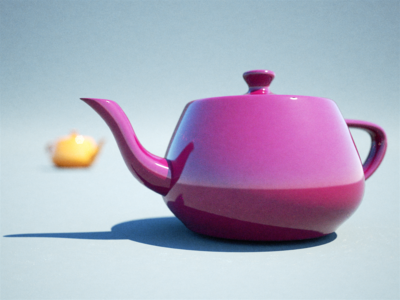
Thin-lens perspective camera
This is the default camera mode, with many familiar settings from standard photography. For more information please see the parent Camera page.
Concrete House scene by Axel Ritter (Impulse Arts)
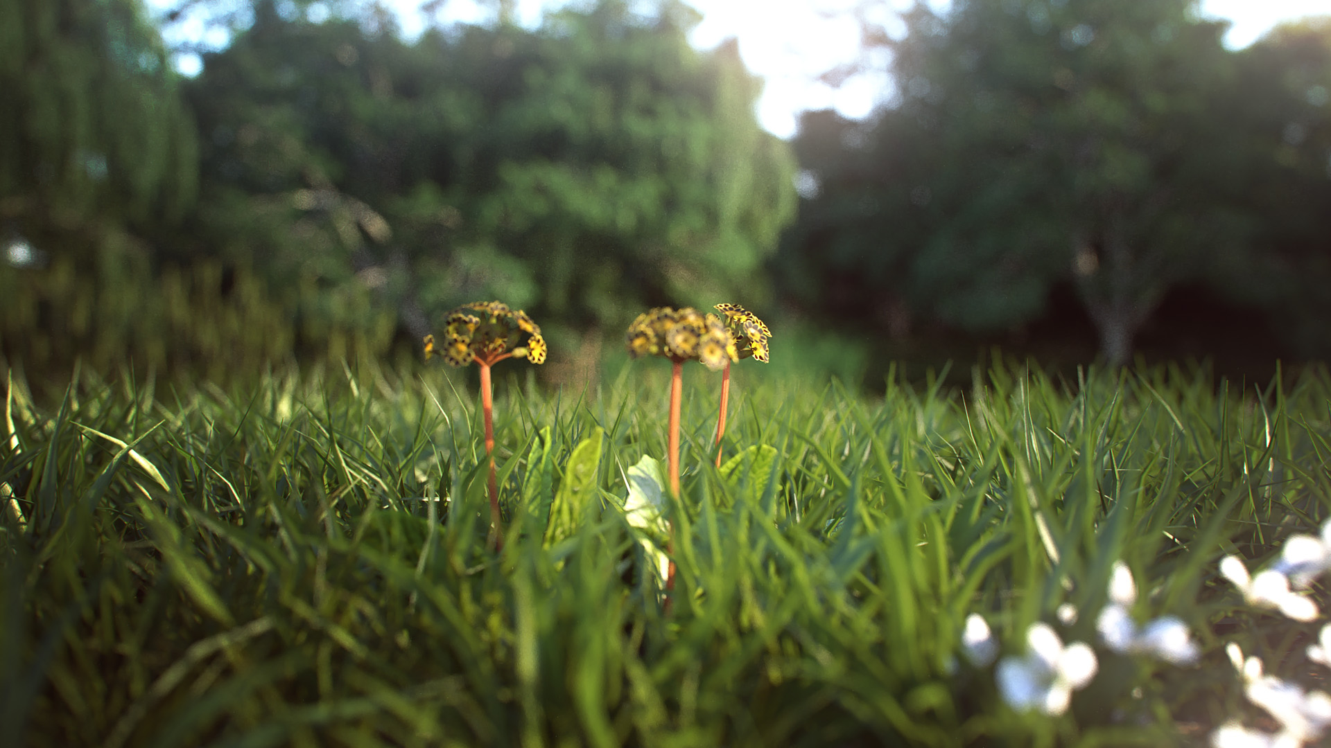
Orthogonal/parallel projection camera
In this mode, there is no foreshortening due to perspective, i.e. objects far away appear the same size as those near to the camera. This is commonly used in architectural visualisation for building plans.
Please note that since there is no perspective in this camera mode, the sensor width needs to be very large in order to be able to image large objects; this can lead to somewhat implausible (though not unphysical!) circumstances in which you have building-sized sensors.
For more information please see the SkIndigo orthographic camera tutorial.

Garden Lobby scene by Tom Svilans (StompinTom)
Spherical projection camera
The spherical projection camera renders a complete 360 degree view at once, which is useful for making environment map renders (for example to use as High Dynamic Range images for illuminating other scenes). It can also be used to render images for 360 degree panorama viewing applications.
Because spherical maps cover twice as many degrees in longitude as latitude, it is recommended to make your spherical renders with aspect ratio 2:1 in X and Y.
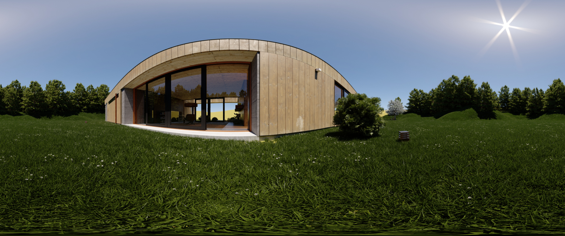
Weekend House scene by Axel Ritter (Impulse Arts)
Tone mapping
Tone mapping changes the brightness and contrast of your image. It can be done at any stage during the render process. Changes to tone mapping will be applied immediately to the rendered image. Tone mapping is non-destructive, so you can play around with the different tone mapping settings without permanently effecting the rendered image. You may want to tone map your image using different settings, and press Save Image to save out several different images.
How it works: Indigo creates a high dynamic range (HDR) image as it renders, and during the tone mapping process this will be converted to a low dynamic range red, green and blue image that can be displayed on your computer monitor. When subsequently saving the image, the user can choose to either save the tone mapped image in JPG, PNG, TIFF or EXR format. Indigo also supports saving of the un-tone mapped HDR image in EXR format for external tone mapping.
Tone mapping method comparisons
Indigo has four different tone mapping techniques that you can choose from: Reinhard, Linear, Camera and Filmic. Here are some comparisons of the different methods, and their strengths and weaknesses, using example scenes from Zalevskiy and Zom-B respectively.
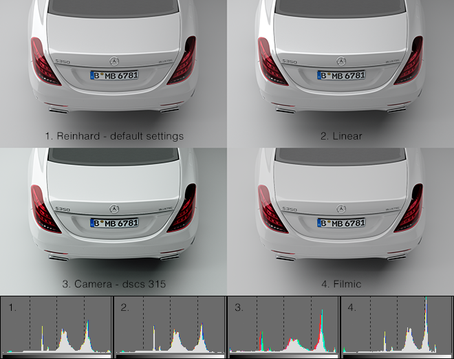
Note how the Camera tone mapping method gives the image a more photographic look with higher contrast and a slight colour tint.
Reinhard is the simplest to use, but once mastered, camera tone mapping can give a nice artistic feel to the renders.
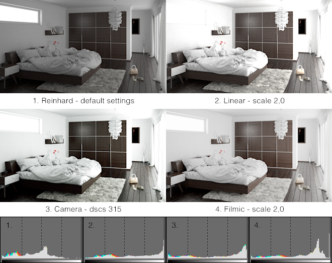
The Filmic tone mapper does a good job with achieving a bright look without burning out the whites.
Linear
The simplest tone mapping method, linear depends on just a single number. Every pixel in the HDR image will be multiplied by this number.
Reinhard
Reinhard is a method based on a paper by Reinhard, Stark, Shirley and Ferwerda from the University of Utah. It is an easy to use tone mapping technique because it automatically adjusts to the amount of light in the scene. It can be tricky to get linear or camera tone mapping to look balanced in scenes where there is an extremely bright light source – the Reinhard method is a good choice for scenes like this.
The default Reinhard settings of prescale=6, postscale=1, burn=2 will give good results for most renders. If you want to adjust the Reinhard method, below is an approximate description of each parameter.
| Prescale | Similar to a contrast control, works by increasing the amount of light in the HDR buffer. |
| Postscale | Works like a brightness control, increases the absolute brightness of the image after it has been tone mapped. |
| Burn | Specifies the brightness that will be mapped to full white in the final image. Can be thought of as gamma control. |
Camera
Camera tone mapping simulates the working of a photographer's camera. You adjust the exposure and ISO settings as you would in a real camera to modify the tone mapping.
The parameters you modify are:
| ISO | The ISO number represents the speed of film that is used. The higher the ISO number, the more light will be collected in the HDR Image. In low light situations, a fast film should be used, such as ISO 1600, and in bright lighting situations, a slow film can be used, such as ISO 100. |
| EV | The exposure value can range from -20 to +20 and represents a correction factor that is applied to the collected light. The higher the EV, the brighter the final image will be. Increasing the EV by one will make the image twice as bright. |
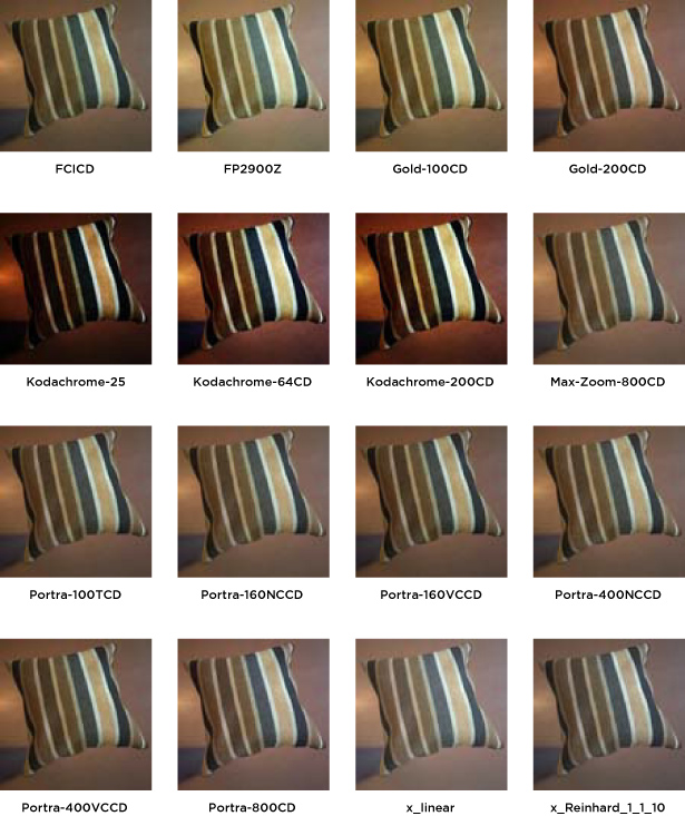
The final parameter is the response function. This specifies the type of film or digital camera to emulate. Different films and cameras emphasise different colours. The response functions are taken from real cameras – for example the images below use Ektachrome 100CD film which is famous for being used by National Geographic in their older photos.
A good default for sunny well-lit scenes is an ISO of 200 and an EV of -5.0.
Here are previews of each of the Camera Response Functions

|

|
|
| Page 1 | Page 2 | Page 3 |
Filmic
Like Linear, this tone mapper has only one control, scale, but it responds quite differently compared to Linear with significantly less contrast at high scale values. This makes it particularly suitable for creating bright images while (to an extent) preventing highlights to burn out.
Colour correction
The Imaging window in Indigo features two controls for simple colour correction: White Point, and Colour Curves.
White Point
This control adjusts the white point of the image via chromaticity coordinates x and y. There are a number of presets to choose from, with the option to edit the white point completely manually.
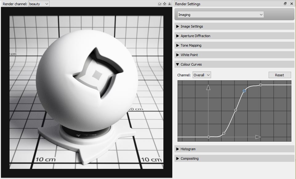
Colour Curves
Colour curves offer great control over tone and colour, right inside Indigo. There are curves for each RGB channel, as well as an Overall curve for control of overall brightness and contrast.
For each colour curve, the x coordinate (e.g. distance along the horizontal axis to the right) is the input value, e.g. how bright a pixel value is before it is transformed by the colour curve. The y coodinate (e.g. distance along the vertical axis upwards) is the output value, e.g. how bright a pixel value will be after it is transformed by the colour curve.
In this example image we are using the colour curve to generate more contrast in the image - in particular to make the blacks blacker and to saturate the brighter grey values towards white. This is achieved by using an S-shaped curve.