Techniques
This is the tutorial and Indigo tricks section.
If you have any requests or suggestions please do not hesitate to send an email to the link provided below.

Vantage - Night by Oscar Johansson
Compositing with shadow pass tutorial
Requirements
This tutorial requires Indigo 3.6.19 or newer.
For this tutorial you will need a car model, standing on a single quad:

You will also need a high dynamic-range environment map (in .hdr or .exr format), plus a backplate image. (which are typically in .jpg format)

Preview of background plate from Moofe

Preview of HDR environment map from Moofe
The environment type should be set to Environment Map, and should be using the high dynamic range environment map mentioned.
Making the shadow pass
You will need to set the ground plane to be a shadow catcher material. To do this, first select the ground plane material with the Pick Material button. Then make the ground material be of Diffuse material type.
Then check the Shadow catcher checkbox at the bottom of the material options.

You may also be able to set the shadow catcher material option directly in your exporter.
Then change the render mode to Shadows:

This should produce a render like so:

For best results, you can make the car object invisible. You can do this by selecting the car object(s) with the Pick Object button, then checking the Invisible to camera checkbox, or by setting the Invisible to camera option for the object in your exporter.
This should produce a result like this:

Making the foreground car render
To make the foreground car render, the car object should be visible to the camera.
The ground object should be invisible to the camera - that is, it should have Invisible to camera checked: (Select the ground object with Pick Object to show these settings)

Now set the render mode to a normal rendering mode like Bidirectional path tracing.
Check the Foreground alpha checkbox. This will make only the car have non-zero alpha:

This should produce a render like this:

Compositing the layers together
We now have 3 layers that we want to composite together:
- The background plate
- The shadow pass
- The foreground render
These layers can be easily composited together in a program such as Photoshop or GIMP:

The final result should look something like this:

Credits: Scene setup originally by hcpiter. Background plate and HDR are by Moofe.
Compositing your scene into an environment
Scene with HDR environment map
Often it is not economical to model and create an environment for your scene to sit in, and it is a common technique to composite elements together to fake it.
There are three main techniques for doing this; the first and easiest is to use alpha compositing. The second method, which gives the best results, is to use an environment map, and the third is to use image planes (or "background cards").
Compositing with alpha channel
The alpha channel specifies the amount of transparency present at each pixel in the rendered image, which is useful for compositing against background images in another image editing application, such as GIMP or Photoshop.
After modelling your scene, lighting it and framing it with the camera, find an image to use as a background that suits your scene. The camera angle, time of day or shadows, and the type of light (incandescent or fluorescent) are all important factors to keep in mind for a matching background image. The resolution of this image should ideally be equal to or greater than the size of the final rendered image.
-
Step 1: Render with alpha channel
To enable rendering with alpha channel output, either click the "Foreground alpha" checkbox in the Indigo render mode settings, or enable it from your exporter package:
SketchUp SkIndigo > Render Settings > Advanced > Tracing Method Cinema 4D Indigo for Cinema 4D Render Settings > Export Settings > Background alpha Blender Blendigo > Render Settings > Alpha render 3ds Max Maxigo > Export > Export Scene > Alpha Mode 
-
Step 2: Insert background image in Photoshop
You can now composite the two using an image editing tool such as GIMP or Photoshop; we'll use Photoshop here for illustration.
-
Put the both images together

-
Create a mask for the real render by selecting the layer and clicking the add mask button Select the alpha layer and copy it.


-
Win:Alt; Mac:Option + click the white mask to select it, and then paste the alpha render onto it.

-
Put an image under it and you're done!


Final composite
Results: Notice the Sun & Sky is still present in the reflections of the windows and looks quite out-of-place. -
Put the both images together
HDR Environment Map
An HDR environment map is an image that fully wraps around your scene to create the effect of having a background, and also emits light. It is important that you use an HDR environment map that has good light, especially if it has the sun in it – the sun is many thousand times brighter than anything else and will only cast good shadows if it has been captured right. This technique gives the best results because all the reflections from the materials will accurately respond to the 'environment' as if it were real. But it is difficult to find a good HDR environment map for free – and can be difficult to make your own. I am using an HDR environment map found from openfootage.net
-
Download an .EXR or .float HDR map. Indigo does not support .HDR files, but there are good converters out there. Try Picturenaut.

Italian field from openfootage - In your render settings, change the environment to Environment Map and set your HDR environment map.
- Render! If the environment map is too dark, or not positioned correctly, you can change the gain for brightness, and rotation to change its position.

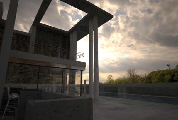
Final render
Results: The scene is effected by the light of the environment map and you can just see reflections of trees from the map in the windows.
Image Planes
This technique is a bit of a cheat really. It involves taking a picture of a background that you would otherwise composite, and texturing them onto a large flat plane. The trick is to get a large enough image that it fills the whole background of the render.
- Create a massive plane that sits directly behind your model, and fills the camera's view. Texture it with your background image and resize it so it fits nicely.
- Copy this front image plane and mirror it behind the camera to create a back-plane.
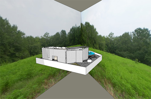
Sketchup scene with massive image planes arranged - To create a convincing background, light must come from the image planes, or they will catch shadows and look fake. Add emission to the textured material, as an emission texture. This will emit light from the surface based on the texture itself. In SketchUp, simply change Emission to SketchUp. I've also set the emission color to white and power to 200.
- Render with sun & sky for good shadows, or you could even just use background colour.

Render with only a front image plane

Final render
Result: (excuse the tonemapping) The bottom has reflections in the windows and a mostly convincing background. It looks alright.
Depth of Field
Depth of field is a phenomena that causes certain parts of an image to blur based on its distance from the camera. It is exploited as a photographic technique for a variety of reasons. A shallow depth of field can be used to accentuate certain parts of a scene, give more detailed information about a subject by exposing just a portion of it, or to remove a distracting background. A wide depth of field puts all elements in focus.
An image is always sharpest at the cameras focal distance, but the depth of field is controlled by the camera's aperture, measured in f-stop. The smaller the f-stop number, the smaller the depth of field; the larger the f-stop, the larger the depth of field.

Wide depth of field, f/22

Shallow depth of field, f/2
IES Lights

IES stands for the Illuminating Engineering Society, which has defined a file format for describing the distribution of light from a light source.
Using only a small, simple emitter such as a single quad, an IES profile will shape the distribution of light emitted from it to match that of a much more complicated light fixture, such as in the examples below:

Digital Photometric data. With the basic Indigo profile Left, and an IES profile Right.
While Indigo is capable of creating real refractions of an accurately modelled light fixture to create this effect, it is far easier to use an IES profile, and the result is much the same. Many manufactures provide IES files for their lights, and it is a great way to add realism to your scene.
You can use an IES viewer to preview these profiles. There is a very good viewing program made by Andrey Legotin that can be found here: http://www.photometricviewer.com/
Setting up the scene
Firstly, we will set up a simple scene to show off the light effects. For this I have made a flat ground plane, to catch the light, and a small, single plane mesh above and perpendicular to it.

A single plane mesh raised off the ground
The plane will be our light-source, so select the it and assign it an emitting material in your Indigo plugin. Since we are working with artificial lighting, go to your environment settings and disable the sun and set a black background.
Hit render and you will get the standard Indigo light render like so:

Render with no IES profile
Adding an IES profile
Open the material editor of your Indigo Plugin, under Emitter Attributes you will find the IES path. Download the zip of IES files here http://www.indigorenderer.com/dist/ies-profiles.zip and link to one. Hit render to view the new IES profile in your scene.

Render with IES profile
Note that Indigo does not support IES profiles with a vertical angle of more than 90degrees and will give an error if attempting to do so.
Optimizing your scene
There are many things you can do to make Indigo render your scene faster, and cleaner, often without compromising quality.
Scene Settings
The first thing you can do is make sure the scene you are rendering is suitable for the power your computer offers.
Light Layers
If there are many light layers used, it will consume a lot of memory. If this exhausts all physical memory the rendering will become extremely slow due to disk access. For more information on light layers, see this section of the manual.
Render resolution
A larger screen resolution, and larger Super Sample factor, will take longer to render, simple because there are more pixels to cover. See Imaging Settings
System Requirements
Check the recommended system requirements to see how your computer compares.
Understand your Render mode
Indigo has several render modes, which control how it chooses where to render, and how. Which mode is appropriate to use varies from scene to scene. Scenes with a lot of specular materials, for example, should be rendered with MLT enabled.
See Render Mode.
Scene design
Some things about the way the scene is made can slow a render down, and likewise speed it up.
Over-saturated colours
If a colour (this includes any colours in texture maps) is over-saturated, it creates an unrealistic conservation of energy as light bounces off it. This can create strange artifacts known as 'fire-flies', along with other problems.
Make sure that no colour is more than 80% saturation, which translates to an RGB no higher than that of 204,204,204.
Glass and liquids
Glass and liquids are one of the things that make Indigo renders stand out. However they can be computationally intensive, and therefore it pays to be aware of how they can affect render times.
Try MLT Bi-Directional path-tracing
MLT is good for clearing glass and liquids, and combined with bi-dir it can help those otherwise hard-to-render areas
Glass around a light source
While it is important to model your scenes as they would appear in the real world to realistically render with Indigo, modeling a light bulb as glass around a light source can greatly lengthen render times. This is because every single ray of light that is emitted has to pass through the glass and reflect & refract its way through it. Effectively this means that all light in the scene is now a caustic. Simply giving the light-bulb's outer shape an emitting material will give the same effect as a real light-bulb, without the extra calculations.
Glossy-Transparent
This material is especially difficult to reproduce efficiently, because of the complex effects it creates. It is strongly suggested that this material not be used to transmit the sole light into a room (as a sky-light for example) See Glossy Transparent
Glass Acceleration
This feature allows glass sheets/panes to be rendered extremely effectively. If the scene has sheets or panes of glass, enabling this will reduce your render times. See Render Settings
Physically correct modelling of glass
Glass is realistically simulated in Indigo, as a (transmission) medium, which requires a little more care when modelling scenes compared to "traditional" renderers. In this section we will focus on glass, however the principles covered here extend to other media (such as water, fog, etc).
We begin with a concise statement of the requirements, and then go into some details. The executive summary is:
When modelling glass in a scene, it cannot be represented as a single surface; there must be at least two (for entering and exiting), and the glass medium occupies the space between them. Furthermore, the surface normals in all cases must point outwards.
Let's start with the first part: glass must be represented as a volume. The following diagram illustrates how light interacts with a glass pane:
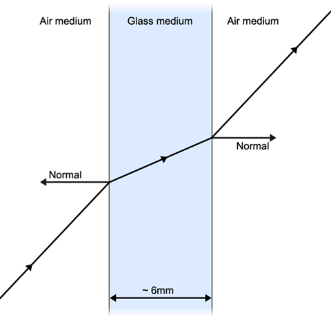
As light travels through the glass medium, its brightness is diminished; this is what gives glass its colour, and it is physically due to the thickness of the glass (and the medium properties), not a "glass colour" modifier at the surface.
If either of the glass faces are not present, the glass volume becomes infinite (since light cannot exit the medium). For example, rendering a house with single-surface glass panes will result in the interior being essentially black, as the light will have lost most of its energy travelling through several metres of glass.
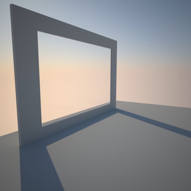
Now that we have described the problem with single-surface glass, we show how to correctly model glass panes. SketchUp is used here, however the same principles apply to all 3D modelling packages.
The simplest way to correctly model a glass pane, is to take a thin box (e.g. a cube squashed in one dimension) and apply an Indigo glass material to it:
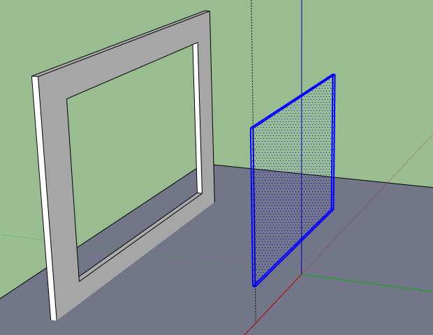
SkIndigo has a default glass material, however if you wish to make your own then you should use the Specular material type with IOR 1.5 and transparency enabled.
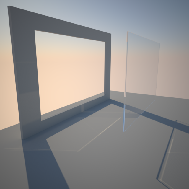
Here is the result rendered in Indigo:
The next step is to insert the glass box into the window frame. Note that we make the glass pane bigger than the opening in the window, allowing the glass faces to intersect the frame, so that the medium is perfectly contained without tiny gaps.
If you want to be more efficient about this, you can remove all faces except for the front and back - since these should be contained entirely inside the solid wall, they cannot affect the rendering and can be safely removed.
With the glass inserted to the frame, we obtain the desired result: